Frequently Asked Questions
Line of Balance Software Overview
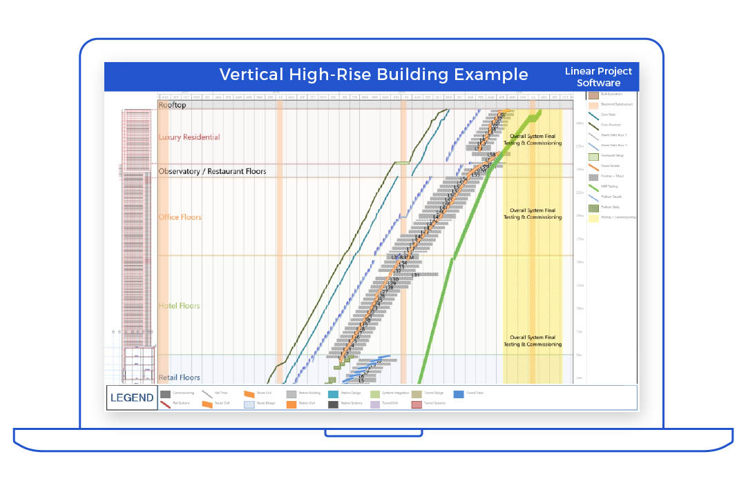
Line of Balance Software is used to prepare line-of-balance charts or line-of-balance diagrams, a type of linear scheduling (see Linear Scheduling Software) or time-distance diagram used in the production and construction industries. For construction projects, line of balance charts and line of balance software are predominantly used in the commercial building and high-rise construction industries to plan, control and report construction schedules, by representing the progress of construction trades across multiple physical areas of construction, such as buildings, floors, rooms or areas.

Line of Balance Software can generate line of balance charts using three methods:

Directly generated from scheduling software applications, examples are Asta Powerproject, or Trimble Vico Office

Produced manually, such as drawing or AutoCad software applications

Produced by linking to scheduling data in scheduling software applications (eg. Turbo-Chart, or excel)

Line of Balance Software Requirements
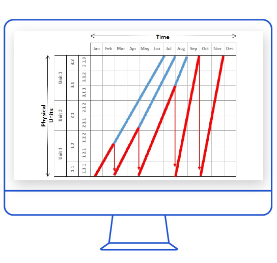
Line of Balance Software creates line of balance charts by producing charts using dual axes. The horizontal axis usually represents time, and the software allows selection of the time period to be show, as hours, days, weeks or months. Gridlines are drawn by the line of balance software to create the date/time grid. The second vertical axis is used to represent the physical work areas.
For Line of Balance charts the software needs to be able to represent physical work areas as a sequence, that may be hierarchical if desired. Typical examples of the physical work areas may be Building, Floor, Area, Room. The physical work axis is presented in the order that the works will be undertaken in, usually in a vertically upward direction. The physical areas at the lower end of the vertical axis are work areas where each trade commences their work, and the areas at the top of the vertical axis are areas where each trade completes their work. The construction sequence is therefore “up” the vertical axes.
Line of Balance Software Schedule Updating
Line of Balance charts typically represent schedule tasks using only lines to represent the works progress across the physical work locations, therefore Line of balance software as a minimum must be able to represent schedule tasks as lines on axes of time and location. As the angle of the lines represents the rate of production for each schedule task, changes made to the schedule that result in changes to production rates must be reflected in the line of balance software to ensure that the current schedule methodology is being represented. This may be either by direct manipulation on the line of balance chart or by refreshing data from the scheduling application.
Production Rate Changes
Where changes to production rates, results in potential clashes with other works, that is, if lines intersect on the line of balance chart, the software must clearly be able to represent all of the clashing schedule tasks, so that action can be taken to either accept the clash or to make further schedule modifications to remove the clash (or error). Actions the line of balance software tool must be able to reflect are:
- Changes to the production rates for activities, ie changing the angle of lines
- Shifting the commencement date/time of tasks such that clashes are avoided
Buffers or Float in CPM
Where gaps exist between lines, these are referred to as “buffers”. Buffers are analogous to Float in CPM scheduling, offering opportunities for tasks to be delayed, without affecting the subsequent tasks. Line of Balance software should clearly represent buffers, and be able to readily reflect changes to the schedule made to introduce or modify buffers.
"Balancing Exercise
Line of Balance software must also be able to visually represent the changes in scheduling that may be made during planning and optimisation of the construction methodology. This exercise is known as “balancing” and it ensures that the construction method operates efficiently by avoiding clashes, downtimes and ensuring adequate buffers exist between construction trades as they progress through the physical work areas.

Line of Balance Software Schedule Updating
Turbo-Chart may be used as a line of balance software tool in two different methods.
Firstly by directly linking to a CPM scheduling tool, and all balancing and buffering conducted in the scheduling tool, Turbo-Chart can then import the schedule data for presentation.
By making task shapes display as line types, and using location start and end values representing the physical work locations, Turbo-Chart is able to produce output as a line of balance software tool. Find out more
Manually created Line of Balance Diagrams
Turbo-Chart may also be used for the second method of manually creating Line of Balance diagrams by drag-and-dropping tasks on the chart itself, by following these steps:
-
Configure the Time axes to represent the intended project duration
-
Rotate the chart to present time along the horizontal axes
-
Configure the Location axes to represent a range of location that covers all the physical units of work to be completed
-
Create Highlighter location bands to name the physical units as bands along the location axes
-
Create a ShapeLibrary with values, shapes, colours etc, that represent each of the work types to be displayed on the line of balance diagram
-
Enable options to create and move tasks
-
Create a task, assign a ShapeLibrary value to this task
-
Move and extend the start and endpoints of this task to cover the start and end dates, and start and end physical area of that task
-
Repeat Steps 7 and 8 for each of the remaining task types
-
Move or modify the tasks to perform the “balancing” task
-
If a task is required to be split, select the source task, then press CTRL+C to copy this task, and CTRL+V to paste a copy of this onto the diagram. Move and position this second task as required
